VxWorks 3D Radar Simulation with WindML and Mesa 4.0
📝 Abstract #
Traditional two-dimensional radar simulation interfaces have limitations in representing target elevation, visualizing three-dimensional motion, and supporting intuitive operator interaction. This article presents the design and implementation of a three-dimensional radar simulation interface on the VxWorks real-time operating system. The implementation ports and trims Mesa 4.0 for use with WindML 3.0, enabling OpenGL-based rendering of radar coverage volumes and moving target tracks. Particular attention is given to drawing-page management and graphics-context ownership, which must be adapted to prevent conflicts between the legacy Mesa driver and the WindML 3.0 window system. The resulting interface provides a three-dimensional view while retaining compatibility with the traditional two-dimensional plan position indicator (PPI) display. This approach improves the visualization of elevation and target motion while reusing the existing radar simulation application.
Keywords: VxWorks, Mesa 4.0, WindML 3.0, radar simulation interface, three-dimensional graphics, OpenGL.
🎯 1. Introduction #
A radar simulation display is the primary graphical interface between a radar information system and its operator. It presents radar coverage, target positions, and movement information, allowing operators to interpret system behavior and assess the spatial relationships between targets and the monitored region.
The clarity of this display directly affects how efficiently operators can understand radar data. An effective radar simulation interface must therefore present spatial information accurately, make target movement easy to follow, and provide intuitive controls for examining the scene.
The principal design requirements are:
- Radar coverage visualization: Display the radar’s coverage volume so that the observable region can be understood in three dimensions.
- Target trajectory visualization: Render target tracks to reveal movement over time rather than displaying only the latest target position.
- Interactive viewpoint control: Allow operators to rotate and zoom the view, adjust the viewing distance, and examine target trajectories from different perspectives.
- Two-dimensional compatibility: Retain the conventional PPI display so operators can switch between familiar planar presentation and three-dimensional visualization.
Traditional radar simulation systems commonly use a two-dimensional PPI display, which represents target bearing and range on a plane. Although effective for many applications, this presentation has limitations when radar data includes elevation and three-dimensional movement.
First, a planar plot does not directly communicate the full spatial relationship between a target and the radar coverage volume. Second, changes in target elevation or pitch may be difficult to interpret because the vertical dimension is compressed into supplementary values or omitted from the primary display. Third, a fixed viewpoint can make complex target trajectories difficult to follow.
These limitations motivate a three-dimensional radar simulation interface that represents target position and movement more directly.
This implementation uses VxWorks as the real-time execution platform and ports Mesa 4.0 into WindML 3.0 to provide the required OpenGL rendering capability. The three-dimensional graphics are integrated into the existing radar simulation display rather than implemented as an entirely separate application. The original two-dimensional presentation remains available, allowing the operator to switch between the two visualization modes.
🏗️ 2. WindML 3.0 and Mesa 4.0 Architecture #
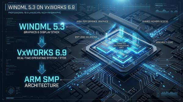
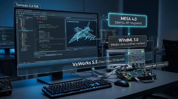
The implementation relies on two principal software components: WindML 3.0, which provides the embedded graphics environment, and Mesa 4.0, which supplies the OpenGL rendering pipeline.
WindML manages the display-facing interfaces, while Mesa performs the three-dimensional graphics operations required by the radar visualization. Integrating the two libraries extends the existing application without replacing its underlying real-time operating system or conventional two-dimensional display functionality.
2.1 WindML 3.0 #
WindML (Wind Media Library) is a multimedia library for VxWorks that provides graphics, font, and related multimedia services for embedded applications.
The WindML 3.0 environment described here retains the basic two-dimensional drawing functionality available in earlier WindML releases. Its primitive graphics operations include:
- Points.
- Lines.
- Rectangles.
- Ellipses.
- Polygons.
These operations are sufficient for drawing conventional PPI elements, including range rings, bearing lines, markers, and other planar graphics.
However, the basic two-dimensional drawing interface does not itself provide the complete three-dimensional transformation and rendering pipeline needed for the proposed radar display. It also lacks the higher-level OpenGL functionality required for convenient 3D scene construction, and its basic primitives do not inherently provide advanced rendering effects such as antialiasing.
Mesa 4.0 addresses this gap by supplying the OpenGL rendering functionality while using WindML as the display-facing graphics environment.
In this architecture, WindML continues to provide the underlying display and window interfaces and supports the existing two-dimensional visualization. Mesa supplies the graphics pipeline used to render the radar coverage volume and target trajectories.
This separation allows the application to retain its existing display functionality while adding three-dimensional visualization through a dedicated rendering layer.
2.2 Mesa 4.0 #
Mesa is an open-source graphics library that implements OpenGL functionality. It provides the rendering operations necessary to construct and display interactive three-dimensional scenes.
Depending on the available platform integration and driver support, Mesa can operate through software rendering or supported hardware-accelerated graphics paths. The implementation described here uses the legacy software-rendering path integrated with WindML.
Mesa 4.0 is selected because its source tree contains the WindML and VxWorks adaptation code required by this development environment. Later Mesa releases do not necessarily preserve the same legacy integration, so replacing Mesa 4.0 with a newer version would require additional compatibility and porting work.
The resulting architecture consists of three logical layers:
- Radar application layer: Maintains radar data, target states, coverage parameters, operator controls, and the display-mode selection.
- Mesa/OpenGL rendering layer: Applies three-dimensional transformations and renders coverage geometry and target tracks.
- WindML display layer: Provides the underlying display and graphics interfaces through which the rendered output is presented.
The application supplies the geometry and state information, Mesa processes and rasterizes the scene, and WindML provides the output path to the display.
Because the implementation uses software rasterization, it does not automatically benefit from GPU acceleration. Its practical performance depends on scene complexity, CPU availability, framebuffer operations, and the timing requirements of the overall radar application.
For additional background, see the VxWorks Mesa OpenGL build and execution guide.
🛠️ 3. Design and Implementation of the Three-Dimensional Radar Interface #
The three-dimensional radar interface extends an existing two-dimensional radar simulation application. Rather than replacing the entire interface, the implementation modifies the radar visualization area to support three-dimensional coverage and target-track rendering.
The central engineering task is integrating Mesa 4.0 with WindML 3.0. This requires building the necessary Mesa components, establishing the WindML rendering interface, and adapting parts of the legacy Mesa driver to the window system’s graphics-context and drawing-page behavior.
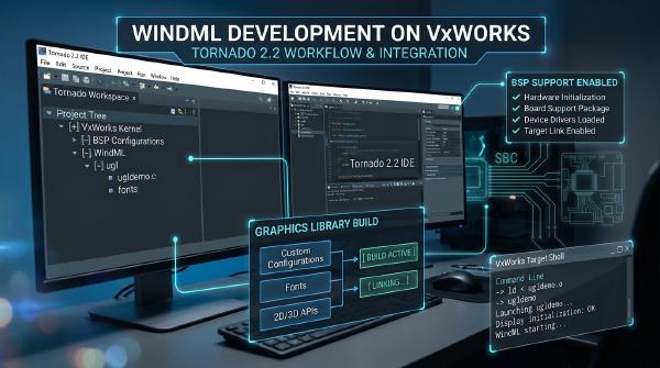
3.1 Porting Mesa 4.0 to WindML 3.0 #
Mesa is open source, allowing the required source files to be selected and compiled into a library for the target environment. The resulting archive can then be linked into the radar simulation application.
The example uses a Tornado development environment with the installation root:
C:\Tornado2.0
The actual installation path may differ; all paths should be adjusted accordingly.
The porting procedure is as follows.
-
Create a downloadable project in Tornado using the SIMNTgnu toolchain.
-
Add the required Mesa 4.0 source files, including the core OpenGL implementation, software rasterizer, transformation and lighting pipeline, WindML backend, GLU utilities, and graphics helpers.
-
Create a
GLdirectory underC:\Tornado2.0\target\hand copy the required public headers into it:gl.hglext.hglu.huglglutshapes.huglMesa.h
The headers must match the naming conventions and files provided by the installed Mesa package. In particular, verify the actual capitalization of the Mesa-specific UGL header in the source distribution.
This directory structure enables application code to include the public interfaces through the standard VxWorks header search path. For example:
#include <GL/gl.h> -
Open the project’s Builds tab and add the Mesa
includeandsrcdirectories to the C/C++ compiler include paths. -
Configure the project to build an archive and compile the required source files into a
.alibrary. -
Add the resulting archive to
PRJ_LIBSin the radar application project and build the downloadable application, producing an.outfile.
Once the archive is built and linked successfully, the application can use Mesa’s OpenGL interfaces through the WindML integration layer.
The source-file selection must be consistent with the installed Mesa 4.0 package and the target toolchain. Missing source files or incompatible build settings may result in unresolved symbols or runtime initialization failures.
The porting approach follows the general workflow used by the Mesa 4.0 and WindML 3.0 integration example, which provides additional context for building and adapting the legacy graphics library.
3.2 Using Mesa 4.0 Through WindML #
The application uses a conventional Mesa rendering sequence adapted to the WindML display environment.
Figure 1. Typical rendering flow for a Mesa application under WindML.

The main steps are:
- Initialize the WindML display environment.
- Create and configure the Mesa/UGL rendering context.
- Make the appropriate graphics context current.
- Set the OpenGL projection and model-view transformations.
- Render the radar coverage volume and target tracks using OpenGL operations.
- Present the rendered output through the configured WindML display path.
- Release rendering resources when the application exits or changes display mode.
During initialization, the application establishes the rendering context and its relationship with the WindML display. During each rendering cycle, it updates the scene state and issues the OpenGL commands required to draw the coverage geometry and target trajectories.
The radar application therefore uses ordinary OpenGL operations for the three-dimensional scene while preserving the existing radar-data processing and two-dimensional drawing functionality.
The most significant adaptations occur during graphics-context creation, drawing-page selection, and resource cleanup. The radar scene’s geometry and per-frame drawing logic can remain largely independent of those integration details.
3.3 Adapting Mesa 4.0 for WindML 3.0 #
The WindML backend supplied with Mesa 4.0 was developed for the WindML 2.0 environment. Although the backend can operate in that environment, using it without modification under WindML 3.0 can cause the window to become unresponsive.
The problem arises from differences in drawing-page management and graphics-context ownership. The legacy Mesa driver manages resources that the WindML 3.0 window system also manages, causing conflicts over which page receives drawing operations and which graphics context controls the window.
The adaptation therefore focuses on two areas:
- Drawing-page selection.
- Graphics-context ownership and destruction.
The OpenGL interface used to construct the radar scene remains unchanged.
3.3.1 Drawing-page management #
The legacy Mesa WindML driver uses two page descriptors, firstPage and secondPage, to represent its drawing and display pages.
In immediate or single-buffer mode, firstPage and secondPage refer to the same page. In double-buffer mode, the driver alternates between drawing into one page and displaying the other.
This model is appropriate only when the driver owns the relevant buffering behavior.
WindML 3.0 manages page selection and presentation through its own window system. If Mesa independently applies its legacy double-buffering behavior, the two layers can attempt to manage drawing and display pages separately. This creates conflicting assumptions about the page being rendered into and the page being presented.
The adaptation is to use the drawing page already selected by WindML 3.0 rather than having Mesa maintain an independent page-switching mechanism.
In the function that creates the UGL/Mesa environment:
- Set the
pageIdoffirstPageto the page identifier of the current WindML drawing page. - Set the buffer address associated with
firstPageto the address of that same drawing page. - Ensure that the Mesa rendering path writes to the page managed by the WindML window system.
These changes align the Mesa drawing target with the actual WindML display buffer.
Figure 2. Updating firstPage to use the current WindML drawing page.

After the change, Mesa’s relevant page identifier and buffer address refer to the drawing surface selected by WindML 3.0.
This prevents the legacy Mesa driver from directing drawing operations to a private page that is inconsistent with the window system’s presentation state.
The exact fields and assignment locations must be verified against the installed Mesa 4.0 source tree because legacy backend implementations can differ.
3.3.2 Graphics-context ownership #
The second issue concerns the graphics context.
The legacy Mesa driver creates its own graphics context during initialization. However, the WindML 3.0 window system already maintains a graphics context for its drawing operations.
If both contexts attempt to control the same window, their state and ownership assumptions can conflict. This is another possible cause of an unresponsive window.
The adaptation replaces the redundant Mesa-owned context with the graphics context used by WindML.
Before the immediate-mode drawing-page setup proceeds:
- Identify the graphics context created by the legacy Mesa initialization path.
- Release the redundant context when it is safe to do so.
- Assign the Mesa context’s graphics-context reference to the existing UGL graphics context supplied by WindML.
- Continue initialization using the context that is valid for the WindML 3.0 window.
After this change, Mesa uses the window system’s graphics context rather than attempting to maintain a separate context for the same window.
Context replacement must be performed carefully. The implementation must distinguish the redundant Mesa-owned object from the WindML-owned context, and it must not destroy a context that remains in use by the window system.
The intent is to share the appropriate drawing context, not to remove the application’s ability to manage its own rendering state.
3.3.3 Safe graphics-context destruction #
Once the Mesa context reference points to the UGL graphics context, the original uglMesaDestroyContext cleanup path must no longer assume that the referenced context is always owned by Mesa.
Unconditionally destroying that context could release an object that belongs to the WindML window system.
The cleanup logic must therefore check context identity before destroying the graphics resource:
- If the context referenced by Mesa is still a separately allocated Mesa-owned context, release it through the appropriate cleanup path.
- If the Mesa context references the same graphics context used by UGL, leave the WindML-owned context intact.
This ownership check prevents Mesa cleanup from invalidating a context that the window system still needs.
The broader implementation principle is that context creation, context sharing, and context destruction must follow a consistent ownership model. A graphics-context pointer alone does not establish ownership of the underlying resource.
3.4 Integrating the Three-Dimensional Radar Scene #
After the Mesa and WindML integration issues are resolved, the radar simulation application can use OpenGL to render the coverage volume and target trajectories.
The three-dimensional view is constructed from the application’s radar data and scene parameters. The relevant application state can be used to determine target positions, update track geometry, and adjust the viewing perspective.
The primary display elements are:
- Radar coverage volume: Represents the region in which the radar can observe targets.
- Target positions: Show current target locations in three-dimensional space.
- Target trajectories: Visualize movement over time to help operators understand direction and motion.
- Interactive viewpoint: Allows the operator to examine the scene from different orientations and viewing distances.
- Two-dimensional PPI view: Retains the conventional planar representation for comparison and operational continuity.
The application can separate data acquisition and radar-state processing from scene rendering. This allows the display to update its geometry based on current radar state without requiring the underlying radar logic to be rewritten for OpenGL.
When implementing the rendering loop, the application should also consider the timing cost of geometry updates, software rasterization, and framebuffer presentation. In a real-time environment, graphics workload must be assessed against the CPU and scheduling resources available to the application.
3.5 Maintaining Compatibility with the Two-Dimensional Interface #
The new three-dimensional display is designed as an extension of the original radar simulation interface.
The conventional two-dimensional PPI view remains available, allowing operators to switch between planar and three-dimensional visualization without leaving the application.
A keyboard command selects the alternate display mode. The application changes the active rendering path while preserving the radar data and the operator’s access to the corresponding display functions.
The two modes serve complementary purposes.
The two-dimensional PPI view provides the familiar range-and-bearing presentation. The three-dimensional view makes elevation and spatial movement more apparent by representing the radar coverage and target tracks within a three-dimensional scene.
To maintain a consistent operator experience, both display modes should use the same underlying radar state and target data. This reduces the risk of presenting different target positions or trajectories in the two views.
The design also allows the existing two-dimensional interface to remain useful when three-dimensional rendering is unnecessary or when operators prefer the conventional PPI presentation.
📊 4. Results and Interface Evaluation #
The implementation was evaluated by comparing the conventional two-dimensional radar simulation display with the new three-dimensional interface in a VxWorks simulator running on Windows.
Figure 3. Comparison of the two-dimensional and three-dimensional radar simulation interfaces.

The three-dimensional view makes the radar coverage volume and target trajectories visible in spatial form. In particular, target elevation and changes in pitch can be understood more directly than in a planar PPI representation.
The two-dimensional mode continues to provide the familiar circular radar display. This retains compatibility with the original application and allows operators to use the presentation appropriate to their task.
Figure 4. Switching from the three-dimensional interface to the two-dimensional interface.

The application uses a keyboard command to switch from the three-dimensional display to the two-dimensional view. Both modes remain part of the same radar simulation interface rather than operating as unrelated applications.
The observed benefits are primarily related to visualization and interface usability:
- Target elevation is represented spatially rather than being confined to a supplementary value.
- Three-dimensional tracks help communicate target movement and spatial relationships.
- The radar coverage volume provides a more direct visual representation of the monitored region.
- The existing two-dimensional PPI display remains accessible.
- The shared interface allows operators to compare planar and spatial presentations of the same radar information.
These observations describe the interface’s visual capabilities. They do not, by themselves, establish quantitative improvements in operator performance or guarantee a particular rendering rate.
Because Mesa uses software rasterization in this configuration, the practical responsiveness of the display depends on scene complexity, target update frequency, CPU load, and the cost of graphics presentation. Those factors should be measured on the intended target before the interface is used in a timing-sensitive operational environment.
⚠️ 5. Engineering Considerations and Limitations #
5.1 Software Rendering Performance #
The Mesa 4.0 implementation described here uses a software-rendering path through the WindML UGL interface. It does not automatically use GPU acceleration.
This is sufficient to demonstrate three-dimensional radar visualization, but rendering performance depends on the CPU resources and workload available to the application.
If the scene contains many tracks, complex geometry, or frequent updates, the application should measure rendering time and overall resource consumption under representative workloads.
Real-time suitability cannot be inferred from visual correctness alone. The graphics task’s execution time and its effects on other activities should be evaluated within the application’s actual scheduling environment.
5.2 Drawing-Page and Buffering Assumptions #
The drawing-page modification addresses the conflict between the legacy Mesa driver’s page-management assumptions and the WindML 3.0 window system.
It should not be interpreted as a general-purpose double-buffering implementation. The application must follow the buffering and presentation mechanisms supported by its selected WindML graphics configuration.
Incorrect assumptions about the active page or framebuffer address can cause display artifacts, stale frames, or an unresponsive window.
5.3 Graphics-Context Lifecycle #
Graphics-context sharing requires a well-defined lifecycle.
Initialization must establish which component owns the context, the rendering code must use the correct context, and cleanup must release only resources owned by the component performing the cleanup.
This is especially important when modifying legacy graphics drivers that were designed for an earlier window-system implementation.
The context-identity check in uglMesaDestroyContext is therefore an essential part of the adaptation, not merely an optional optimization.
5.4 Legacy Software Compatibility #
Mesa 4.0 and WindML 3.0 belong to a legacy embedded graphics environment. Their source structures, APIs, and build assumptions are version-specific.
Porting the implementation to a different Mesa release, WindML version, processor architecture, or graphics driver requires verifying the relevant context, buffering, and initialization interfaces.
The source modifications described here apply to the integration behavior of the legacy driver. They should not be assumed to work unchanged with modern OpenGL implementations or newer VxWorks graphics stacks.
5.5 Operator Interface Validation #
Three-dimensional rendering can improve the visibility of elevation and spatial relationships, but a more realistic-looking display is not automatically a more effective operator interface.
A practical evaluation should examine whether the coverage volume is interpretable, whether target tracks are distinguishable, whether viewpoint controls are predictable, and whether switching between the two modes preserves a consistent presentation of radar state.
The interface should also remain responsive under expected workload conditions. These checks complement the software integration tests and help determine whether the visualization is suitable for the intended application.
✅ 6. Conclusion #
This article presents the design and implementation of a three-dimensional radar simulation interface on VxWorks using Mesa 4.0 and WindML 3.0.
The implementation extends the conventional two-dimensional radar display by adding an OpenGL-based representation of the radar coverage volume and target trajectories. This makes target elevation, pitch, and spatial movement easier to interpret while preserving access to the original PPI display.
The key integration work lies in adapting the legacy Mesa WindML driver to the WindML 3.0 window system. Aligning Mesa’s drawing-page references with the active WindML drawing surface prevents conflicting page management. Reusing the appropriate UGL graphics context and introducing an ownership-aware destruction check address the corresponding graphics-context conflicts.
These changes allow the radar application to retain its OpenGL rendering logic while integrating it with the existing WindML display environment.
The resulting architecture demonstrates how a legacy embedded graphics stack can be extended to provide three-dimensional radar visualization without replacing the existing two-dimensional interface. Its practical suitability, however, depends on validating graphics-context ownership, framebuffer behavior, rendering performance, and real-time resource usage on the target platform.