VxWorks Device Driver Development: Serial and Ethernet Drivers
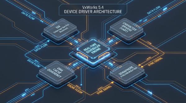
Device drivers are a critical part of embedded operating system development. They connect hardware peripherals to the operating system’s I/O subsystem, allowing applications to access devices through standardized interfaces rather than directly manipulating hardware registers.
VxWorks, developed by Wind River, is widely used in embedded systems that require predictable real-time behavior, reliable interrupt handling, and configurable system components. Developing drivers for a new hardware platform typically involves understanding the VxWorks startup sequence, configuring the Board Support Package (BSP), establishing a host–target debugging environment, implementing hardware-specific interfaces, and integrating the resulting drivers into a bootable system image.
This article presents a practical approach to VxWorks device driver development, using an I8250-compatible UART serial driver and a Realtek RTL8139 Ethernet driver as representative examples. The serial driver demonstrates character-device integration with the VxWorks I/O system, while the Ethernet driver illustrates the Enhanced Network Driver (END) model and its integration with the network stack.
The development workflow covers BSP configuration, boot-image generation, Tornado cross-debugging, hardware initialization, interrupt handling, buffer management, driver registration, and target-side verification. Although the examples originate from an x86-based platform, the underlying engineering principles apply to many VxWorks-based embedded systems.
🏗️ 1. VxWorks Architecture and BSP Configuration #
VxWorks combines a real-time kernel with hardware-specific support, an I/O subsystem, networking components, and optional file systems and other services. Device drivers must integrate with the appropriate subsystem while respecting the platform’s interrupt, memory, and initialization requirements.
The main components relevant to driver development are:
- Wind real-time kernel: Provides task scheduling, synchronization, interrupt-related services, and core operating system functionality.
- Board Support Package (BSP): Implements platform-specific initialization, memory configuration, interrupt setup, and board-level device support.
- I/O system: Provides common interfaces for character-oriented devices and other supported device classes.
- Network stack and MUX layer: Connect network drivers to protocol implementations through a standardized interface.
- File system and supporting components: Provide optional services required by the target application.
1.1 Bootrom and VxWorks Image Startup #
The boot process typically involves two software images:
- Bootrom image: Performs early hardware initialization and loads the main VxWorks image.
- VxWorks image: Contains the kernel, configured system components, and application code.
For a traditional ROM-based x86 target, the startup sequence can be summarized as follows:
romInit()establishes the initial processor state, configures essential hardware state, and prepares the system for subsequent initialization.romStart()transfers control to the next boot stage, including loading or relocating the VxWorks image into RAM and decompressing it when required by the image format.sysInit()and related BSP initialization routines establish the platform’s execution environment and transfer control into the system initialization path.usrInit()performs early operating system initialization and eventually invokeskernelInit()to establish the multitasking environment.- The root task,
usrRoot, completes higher-level system initialization, including the installation and startup of configured drivers and services.
The precise sequence varies with the VxWorks release, processor architecture, BSP implementation, and boot configuration. Developers should consult the startup source for their specific target rather than assuming that every BSP follows an identical call sequence.
1.2 BSP Files and Configuration Parameters #
In classic VxWorks and Tornado environments, BSP configuration commonly involves files such as:
| File or component | Primary responsibility |
|---|---|
config.h |
Defines BSP configuration options and enables selected components |
sysLib.c |
Implements system-level hardware initialization and BSP services |
sysSerial.c |
Provides serial-device support where the BSP uses this organization |
romInit.s |
Implements low-level startup in assembly |
| BSP Makefile | Defines image-building rules, compiler options, and source dependencies |
The actual file organization depends on the VxWorks version and BSP.
Important configuration parameters include the memory map, interrupt-vector definitions, boot-device selection, network settings, and driver inclusion macros. For example, a legacy END-based network driver may require a component macro such as INCLUDE_END and a driver-specific inclusion macro supported by the BSP.
These names are not universal across all VxWorks releases. Modern VxWorks 7 projects commonly use a component-based configuration model and the VxBus driver framework, while classic VxWorks 5.x and 6.x systems may use more statically configured BSP and END integration.
After changing the configuration, rebuild the relevant Bootrom and VxWorks images using the development environment appropriate to the target.
For a classic Tornado-based implementation, the VxWorks 5.4 Device Driver Development guide provides additional context on legacy driver interfaces, BSP integration, and debugging.
1.3 Establishing the Host–Target Debugging Environment #
A host–target development environment separates compilation and debugging from execution on the embedded target.
In a traditional Tornado workflow:
- The host runs the IDE, compiler, linker, source-level debugger, and target communication tools.
- The target runs the Bootrom or VxWorks image and provides the services needed for debugging.
- The WDB agent supports target debugging and communication with host-side development tools.
- The WTX protocol supports target-server operations in applicable legacy Tornado environments, including facilities for downloading and manipulating target objects.
The exact protocols and services depend on the Tornado version and target configuration.
Before implementing a new driver, verify that the target boots consistently, the console works, the host can communicate with the target, and symbols and source files are available for debugging.
This initial validation is important because a driver failure can otherwise be difficult to distinguish from a BSP, boot, or target-communication problem.
🔌 2. Serial Device Driver Design: The I8250 UART #
The I8250-compatible UART is a useful starting point for device driver development because its register interface is relatively simple and its behavior is easy to observe.
In classic VxWorks systems, serial terminals are commonly integrated with the I/O system through ttyDrv and supporting terminal routines. Applications can then use standard operations such as open(), read(), write(), and ioctl() rather than manipulating UART registers directly.
The overall design separates hardware-specific register operations from the character-oriented interface presented to applications.
2.1 Driver Data Structures and Hardware Abstraction #
The driver should maintain a device-specific structure containing the information required to operate each UART instance.
Typical fields include:
- UART base address or mapped register address.
- Interrupt vector and interrupt level, where applicable.
- Baud-rate divisor and serial format settings.
- Transmit and receive buffer pointers.
- Ring-buffer head and tail indices.
- Interrupt and device status information.
- Synchronization objects used to coordinate tasks and interrupt handlers.
Hardware access should be encapsulated in small helper functions or macros. This reduces duplicated register manipulation and makes it easier to adapt the driver to different I/O address mappings or memory-mapped UART implementations.
Register definitions must follow the actual controller documentation. Although I8250-compatible devices share a common programming model, implementations can differ in FIFO support, register behavior, interrupt routing, and available extensions.
2.2 Initialization and Device Registration #
The initialization routine configures the UART and connects it to the VxWorks I/O system.
A typical sequence includes:
- Validate the device configuration and register base address.
- Disable UART interrupts while configuring the device.
- Set the baud-rate divisor and serial communication format.
- Configure FIFO operation when supported.
- Clear pending status conditions and initialize software buffers.
- Connect the interrupt handler to the appropriate interrupt vector.
- Enable the required UART interrupt sources.
- Register or create the terminal device through the appropriate VxWorks serial and I/O interfaces.
The precise registration sequence depends on whether the implementation integrates with the existing BSP serial framework or provides a separate character-device implementation.
For an early boot console, serial support may need to be available before the full kernel initialization completes. In that case, the early-console implementation and the normal runtime driver should be designed to avoid conflicting access to the same hardware.
2.3 Transmit and Receive Paths #
A robust serial driver separates data movement from application-level operations.
For transmission, an application writes data through the device interface. The driver places the data into a transmit buffer and either feeds the UART directly or enables transmit interrupts to move data into the transmit holding register or FIFO.
For reception, the UART signals that data is available. The interrupt handler retrieves incoming bytes and places them into a receive ring buffer. A task-level routine subsequently delivers those bytes to waiting readers.
Ring buffers help decouple interrupt context from task context, allowing the interrupt handler to perform bounded operations without waiting for an application to consume data.
Buffer overflow, transmit starvation, and concurrent access must be handled explicitly. Depending on the design, synchronization may use carefully bounded critical sections, interrupt masking, or suitable synchronization primitives.
An interrupt service routine should not perform operations that can block. When more substantial processing is required, the ISR should record the event and defer the work to task context.
2.4 Interrupt Handling #
The I8250 interrupt handler examines the interrupt identification register to determine which event requires service.
Common causes include:
- Received data available.
- Receive-data timeout, where supported.
- Transmitter holding register empty.
- Line-status changes or errors.
- Modem-status changes, if the application uses modem-control signals.
The handler must service the actual interrupt source and acknowledge or clear conditions as required by the device’s register semantics. Incorrect interrupt handling can lead to repeated interrupts, lost input, or a stalled transmit path.
For real-time performance, the handler should remain short and predictable. Extensive logging, blocking operations, and unnecessary processing should be avoided in interrupt context.
2.5 Serial Driver Verification #
Serial testing should begin with basic hardware access and progress toward complete terminal functionality.
Recommended tests include:
- Confirming that initialization produces the expected register values.
- Verifying the configured baud rate and serial format.
- Checking console output and input.
- Running loopback tests when supported by the hardware.
- Testing sustained transmit and receive traffic.
- Injecting or simulating buffer saturation and communication errors.
- Confirming correct behavior under concurrent task activity.
Because the serial console is often the primary source of diagnostic output during early system development, its reliability directly affects the efficiency of subsequent driver debugging.
🌐 3. Network Device Driver Design: RTL8139 and the END Model #
The Realtek RTL8139 is a PCI Ethernet controller historically used in x86 systems. Its PCI interface makes it a representative example for studying device discovery, register access, DMA, interrupt handling, and network-stack integration.
In classic VxWorks environments, the Enhanced Network Driver (END) model provides a standardized interface between network drivers and the MUX layer. The MUX allows multiple protocol components to share a network interface without requiring each driver to implement the protocols independently.
The END model is particularly relevant to legacy VxWorks and Tornado systems. Modern VxWorks 7 development commonly uses VxBus, so a new implementation should follow the driver framework supported by the specific release rather than automatically porting a legacy END driver unchanged.
For a modern comparison, see VxBus Driver Development: A Complete Guide for VxWorks Developers.
3.1 PCI Discovery and Hardware Initialization #
The RTL8139 driver must first identify the device and determine how the operating system can access its registers and interrupts.
The initialization process generally involves:
- Enumerating the PCI bus and identifying the controller through its vendor and device identifiers.
- Reading the PCI configuration space to determine the applicable Base Address Registers (BARs) and interrupt configuration.
- Enabling the required PCI device resources and bus-mastering capabilities.
- Mapping or accessing the controller’s register space using the platform’s supported PCI services.
- Allocating suitable memory for receive buffers and transmit data.
- Configuring the controller’s MAC, receive, and transmit registers.
- Connecting the interrupt handler.
- Registering the network interface with the END and MUX infrastructure.
The PCI configuration space must be interpreted according to the device and platform. A BAR can describe I/O-port space or memory-mapped resources; it should not be treated as an ordinary physical memory address without checking its type and the operating system’s mapping requirements.
3.2 DMA and Buffer Management #
The RTL8139 uses DMA to transfer packet data between system memory and the network controller. DMA allows the device to access packet buffers without requiring the CPU to copy every byte through programmed I/O.
However, DMA introduces requirements that must be addressed explicitly:
- Buffers must satisfy the device’s alignment and addressability constraints.
- The device must be given valid DMA addresses rather than arbitrary CPU virtual addresses.
- Cache coherency must be handled according to the processor, memory system, and DMA API.
- Buffer ownership must be tracked so that software and hardware do not access the same region incompatibly.
- Receive-ring wraparound and buffer exhaustion must be handled correctly.
The exact requirements depend on the target platform and its DMA implementation. A buffer that works on a simple x86 configuration may not be valid on a different processor architecture.
3.3 END Entry Points and Interface Registration #
A classic END driver typically exposes a set of functions required by the END interface.
The endLoad() entry point initializes or loads the driver instance and provides the interface information expected by the network subsystem. Other operations support device startup and shutdown, packet transmission, address configuration, multicast filtering, and statistics reporting.
The driver must follow the exact interface contract for its VxWorks version. The following descriptions summarize the responsibilities of a typical implementation.
Initialization and loading
The driver validates configuration parameters, allocates resources, initializes the controller, prepares receive and transmit structures, and creates the network interface representation required by END.
Packet transmission
The transmit path accepts outgoing packets from the network subsystem, prepares the data for the controller, updates the appropriate transmit registers or descriptor structures, and starts DMA transmission.
When transmission completes, the driver reclaims resources and updates relevant statistics.
Packet reception
The receive path identifies completed receive operations, validates packet lengths and status information, and delivers valid Ethernet frames to the MUX using the required network-buffer interfaces.
Invalid packets, incomplete frames, and buffer overruns must be handled according to the controller’s documented behavior.
Interrupt processing
The interrupt handler distinguishes receive, transmit-completion, and error conditions. It acknowledges serviced events, records relevant statistics, and schedules any deferred work required by the driver design.
As with the serial driver, interrupt processing should be bounded. Network packet processing and recovery operations that could take substantial time should be deferred when the architecture permits.
3.4 Error Handling and Network Maintenance #
A production-quality network driver must handle more than successful packet transmission.
Important conditions include:
- Receive-buffer overflow.
- Transmit timeouts.
- Unexpected interrupt status.
- Link-state changes.
- Invalid or oversized packets.
- Resource-allocation failures.
- Controller initialization failures.
- Hardware reset and recovery requirements.
The driver should expose meaningful error counters and status information through the interfaces supported by the relevant VxWorks release.
Multicast filtering, interface statistics, and link-status handling should also follow the applicable END or network-stack contract.
Once the driver is implemented, the BSP or project configuration must include the required network components and driver registration. The exact component macros and device-table mechanisms vary across VxWorks generations.
🧪 4. Integration, Cross-Debugging, and Target Verification #
A driver that compiles successfully is not necessarily a functioning driver. Verification must cover hardware initialization, normal data transfer, interrupt behavior, error recovery, and integration with the operating system.
The Tornado host–target environment provides a practical way to inspect registers, download code, set breakpoints, examine memory, and diagnose failures while the driver runs on the target.
4.1 Serial Driver Tests #
The I8250 driver should be validated before depending on it for extensive network debugging.
A useful test sequence is:
- Verify UART register access and initialization.
- Confirm console output at the expected baud rate.
- Test incoming characters and line handling.
- Run loopback tests where supported.
- Exercise sustained input and output.
- Test buffer boundaries and interrupt recovery.
- Verify operation while other tasks are active.
If the serial driver is also responsible for the system console, preserve a reliable diagnostic path while testing other components.
4.2 Ethernet Driver Tests #
Network verification should progress from low-level hardware checks to protocol-level tests.
Begin by confirming PCI enumeration, BAR configuration, interrupt assignment, controller initialization, and DMA-buffer setup. Next, verify link status and packet transmission and reception.
Higher-level tests can then include:
- Ping or equivalent connectivity tests.
- Packet transmission and reception under sustained load.
- FTP transfers between the host and target, where the relevant services are available.
- Repeated interface initialization and shutdown.
- Error handling and recovery under abnormal conditions.
- Concurrent network activity and other real-time workloads.
Successful ping responses alone do not establish that a driver is robust. Sustained transfers, interrupt-load testing, error injection where feasible, and memory-integrity checks provide stronger evidence of correctness.
4.3 Common Integration Problems #
Several low-level issues frequently complicate driver development.
| Symptom | Possible cause | Diagnostic approach |
|---|---|---|
| No serial output | Incorrect UART base address, clock, or baud-rate configuration | Inspect register values and verify the hardware clock configuration |
| Repeated interrupts | Interrupt source not cleared or incorrectly acknowledged | Inspect interrupt status and device-specific clearing semantics |
| Missing receive data | Incorrect interrupt setup, FIFO handling, or buffer management | Trace receive status and ring-buffer indices |
| Ethernet device not detected | PCI enumeration or resource configuration failure | Inspect PCI vendor/device IDs and BAR values |
| DMA failures | Invalid DMA address, alignment, or cache handling | Validate the platform DMA requirements and buffer ownership |
| Intermittent packet loss | Receive-ring overflow, incorrect packet handling, or interrupt latency | Examine driver statistics and trace receive processing |
| FTP or other large transfers fail | Packet-path defects, resource exhaustion, or network configuration errors | Test packet sizes and transfer loads incrementally |
A disciplined debugging process isolates one layer at a time. Confirm hardware access first, then interrupts, then buffer management, and finally integration with higher-level interfaces.
4.4 Integrating the Drivers into the Final Image #
Once the drivers pass their functional tests, integrate them into the BSP or system project.
For a classic VxWorks build, this may involve adding the driver source files to the appropriate build rules, registering initialization routines, enabling component macros, and configuring the relevant device tables.
Rebuild the required system image and verify that the drivers initialize correctly during a clean boot. Repeat the main tests against the integrated image rather than relying solely on manually downloaded driver objects.
The resulting image may be portable to other x86-compatible boards, but only when their hardware resources, interrupt routing, PCI configuration, memory layout, and peripheral implementations are compatible. Portability should be verified, not assumed.
⚙️ 5. Engineering Considerations for Reliable VxWorks Drivers #
The I8250 and RTL8139 examples illustrate several principles that apply to embedded driver development more generally.
5.1 Keep Hardware Access Separate from the Interface Layer #
Hardware-specific operations should be isolated from the character-device or network-interface implementation.
This separation makes it easier to reuse the driver logic, replace the underlying controller, and test components independently. It also reduces the risk that hardware-specific assumptions will leak into application-facing interfaces.
5.2 Respect Interrupt and Task Context #
Interrupt handlers must avoid blocking operations and should perform only the work necessary to acknowledge events and preserve device state.
Long-running processing should be deferred to task context where appropriate. Buffer management and synchronization must be designed to prevent races between the ISR and tasks.
5.3 Validate Every Hardware Assumption #
Register maps, interrupt behavior, DMA constraints, cache attributes, and device reset sequences must come from the applicable hardware documentation and platform implementation.
Legacy driver code should not be assumed to work unchanged on a new BSP or a newer VxWorks release.
5.4 Test Failure Paths as Well as Normal Operation #
A driver should handle timeouts, allocation failures, malformed packets, buffer exhaustion, unexpected interrupts, and initialization errors.
Testing should demonstrate not only that the device works under ideal conditions, but also that faults are detected and managed without compromising the rest of the system.
5.5 Match the Driver Model to the VxWorks Release #
Classic VxWorks versions commonly use legacy I/O and END interfaces in configurations built with Tornado. VxWorks 7 introduces a more modular driver architecture centered on VxBus, with support for modern device discovery and hardware description mechanisms.
When porting an existing driver, review the target release’s supported interfaces, initialization model, DMA services, interrupt APIs, and component configuration before beginning implementation.
📌 6. Conclusion #
Developing device drivers under VxWorks requires more than translating a hardware register map into C code. The driver must fit into the BSP startup sequence, use the correct operating system interfaces, handle interrupts predictably, manage memory safely, and cooperate with the relevant I/O or network subsystem.
The I8250 UART example demonstrates how to integrate serial hardware with a character-oriented interface, using initialization routines, transmit and receive buffers, and interrupt-driven data transfer.
The RTL8139 example illustrates the additional complexity of PCI network devices, including hardware discovery, DMA, packet processing, interrupt management, and integration with the classic END/MUX architecture.
Together, these examples establish a reusable development workflow:
- Understand the target hardware and the VxWorks version.
- Configure and validate the BSP and boot process.
- Establish reliable host–target debugging.
- Implement the driver using the appropriate interface model.
- Verify hardware access, interrupts, data transfer, and error handling.
- Integrate the driver into the system image and retest on the target.
The central engineering lesson is that reliable embedded drivers depend on clear interface contracts, careful hardware analysis, disciplined interrupt handling, and systematic verification. Applying these principles provides a solid foundation for extending VxWorks to new boards and peripherals while preserving the real-time behavior expected of an embedded operating system.